
产品介绍
ZK-03B三相可控硅整流触发器使用说明书
Operation Instructions for ZK-03B Three Phase Silicon controlled voltage-adjusting trigger
一、概述(General)
ZK-03B可控硅调压触发器采用集成电路器件工艺制造,控制电路采用电压负反馈连接,其输出电压稳定、抗干扰能力强,质量可靠。仪表面板设有“输出设定”手动调节输出电压旋钮以及限幅功能,以满足用户对控制系统的需要。
ZK-03B Silicon controlled voltage-adjusting trigger adopts integrate circuit technology, control circuit adopts the connection of voltage negative feedback, its output voltage is steady, and it has strong anti-interference ability and reliable quality. On the instrument face-plate, the knob of Output Setting manual adjustment output voltage has been set and it has the amplitude limit function to meet the need of the customer to the control system.
二、技术指标(Technical index)
1、输入信号:0-200V。
Input signal:0-200V
2、输出信号:三相脉冲输出,每相输出正脉冲。
Output signal: three phase pulse output, output positive pulse per phase
脉冲幅值≤4V(20负载);
脉冲宽度≥0.2ms;
电压调节范围:0-220V。
Pulse amplitude ≤4V (20 load);
Pulse width≥0.2ms;
Range of voltage adjustment: 0-220V
3、配用可控硅:KP管(单向)1000A以下。
Equipped with thyristor: KP transistor (Unidirectional), less than 1000A
4、电源:~380V±10%,50HZ(三相三线)。
Power source: ~380V±10%,50HZ (three phase three wire)
5、工作环境:温度<50℃,相对湿度<85%.
Working conditions : temperature <50℃, relative humidity <85%.
6、重量: ≤2kg
Weight: ≤2kg
7、消耗功率:约6W
Consumption power: about 6W
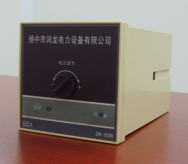
三、面板布置说明(Instructions for face -plate arrangement)
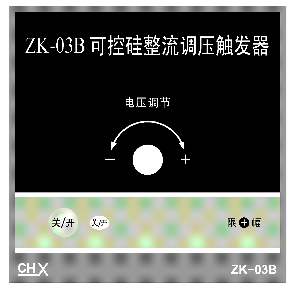
1、“电压调节”---手动调节输出电压。
Voltage adjustment-----adjust the output voltage manually
2、“关/开”---启、停触发可控硅。
Off/on-----switch on/off the trigger thyristor
3、“限幅”---设定输出电压上限。
Amplitude limit-----Set the upper limit of output voltage
四、安装与接线(Mounting and wiring)
1、 外形尺寸:(长×宽χ×深):96×96×178
Overall dimension: (lengthXwidthXdepth); 96×96×178
安装面板开孔尺寸:92×92
Hole size of mounting face-plate: 92X92
2、仪表接线端子如图所示
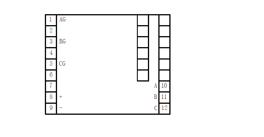
Instrument wiring terminals as the following diagram
3、 接线端子与电路连接(仅供参考)
Wiring terminals and circuit connection (only for reference)
图中A、B、C、AG、BG、CG、分别与仪表端子号对应连接。
A, B, C, AG, BG, CG in the diagram should be corresponding to the instrument terminals Number.
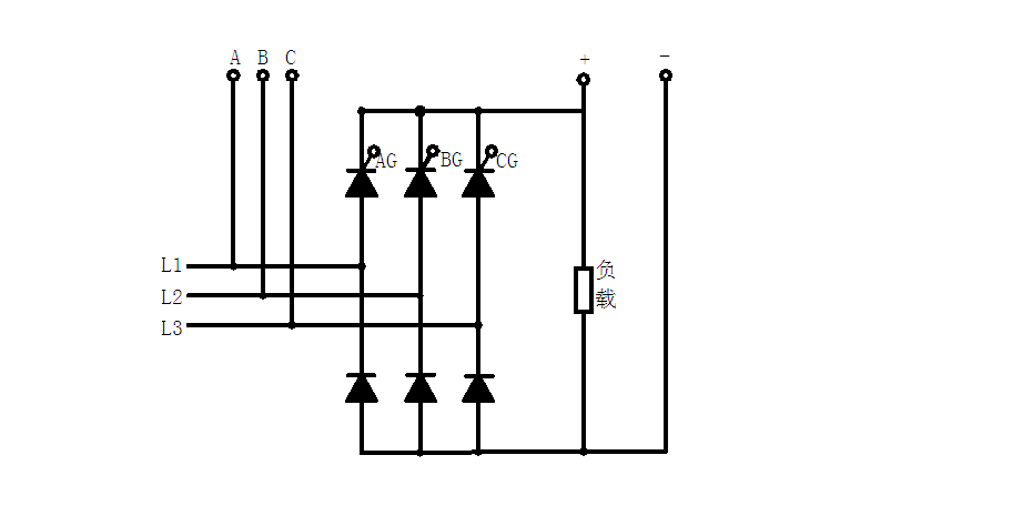
说明:电源电缆按相序连接。
Note: The cable of the power source should be connected according to the phase sequence.
五、仪表的使用方式(Usage of instrument)
1、查各接线端子接线无误、可接通电源,将“输出调节”旋纽逆时针旋到始点。
After examining every wiring terminals being wired correctly, switch on the power source and revolve the knob of Output Adjustment anticlockwise to the position of the initial point.
2、“关/开”键,“关/开”工作指示灯亮。
Off/On key, Off/On running indication light is on.
3、 调整“输出调节”旋纽,调整至现场需要的输出电压(必须接入负载)。
Adjust the knob of Output Adjustment, adjust the required output voltage on site (the load must be connected).
4、 再按“关/开”键,仪表停止工作。
Press the key of Off/On again, the instrument will stop running.
5、 仪表具有断电自动关机功能。
The instrument has the cut-off function automatically after power-off.
